

KiwiH743-Wing Flight Controller
Overview
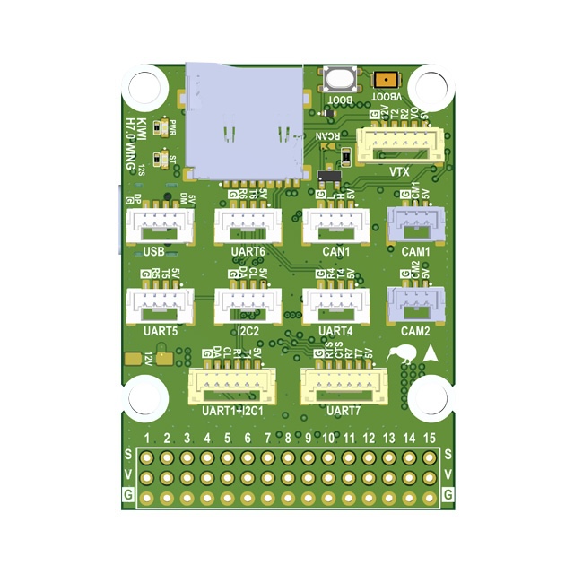
The KiwiH743-Wing is a Pixhawk-format flight controller system consisting of two boards: a Flight Controller and a Power Distribution Board (PDB). Designed for expendable quadcopters and long-range fixed-wing drones. Ready to use with Rover, Wing, Quadcopter, and Hexacopter configurations.
Premium features: GPS-less takeoff, IRC Tramp VTX control, VRX integration (TBS Fusion, Skyzone Steadyview).
Firmware
- ArduPilot KiwiH743-wing.zip
- Betaflight
Features
- STM32H743 MCU (480 MHz, 2 MB flash)
- 12S power supply
- 5V, 6/7V, 9/12V 5A BECs
- ICM-42688P and ICM-45686 with power and hardware signal filtering
- BMP388 barometer
- Dual camera input, switchable
- 8 motors + 7 servos (15 PWM outputs)
- 5 UARTs, UART7 with flow control
- 1 SPI, 1 I2C, FDCAN
- 5 GPIOs, 2 relay outputs, 9/12V switch
- Analog + digital VTX output
- STM32G4 OSD
- SD card via SDMMC
- 40 x 42 mm board, 36 x 39 mm mounting holes
Technical Specifications
Processor
| Parameter | Value |
|---|---|
| MCU | STM32H743 |
| Architecture | ARM Cortex-M7 |
| Max Frequency | 480 MHz |
| Flash | 2048 KB (2 MB) |
| Crystal | 16 MHz external oscillator |
Sensors
| Sensor | Part | Notes |
|---|---|---|
| IMU 1 | ICM-42688P | External clock, hardware filtered |
| IMU 2 | ICM-45686 | Hardware filtered |
| Barometer | BMP388 | |
| OSD | STM32G4 | Analog video overlay |
Power
| Rail | Voltage | Current |
|---|---|---|
| Input | 12S (up to ~50V) | |
| BEC 1 | 5V | 5A |
| BEC 2 | 6/7V | 5A |
| BEC 3 | 9/12V | 5A |
Mechanical
| Parameter | Value |
|---|---|
| Board size | 39 x 39 mm |
| Mounting holes | 30.5 x 30.5 mm |
Serial Ports
| Serial | UART | TX Pin | RX Pin | Notes |
|---|---|---|---|---|
| Serial 1 | UART1 | PB14 | PB15 | |
| Serial 2 | UART2 | PD5 | PD6 | |
| Serial 3 | UART3 | PD8 | PD9 | |
| Serial 4 | UART4 | PD1 | PD0 | |
| Serial 5 | UART5 | PB13 | PB12 | |
| Serial 6 | UART6 | PC6 | PC7 | |
| Serial 7 | UART7 | PE8 | PE7 | RTS: PE9, CTS: PE10 |
| Serial 8 | UART8 | PE1 | PE0 | OSD UART |
GPIOs, Relays, and AUX
Dedicated GPIO Pads
| Pad | Pin | GPIO | Default | ArduPilot Relay Config |
|---|---|---|---|---|
| CAM SW | PE2 | 100 | RELAY1 | RELAY1_PIN=100 (hwdef default) |
| RELAY 1 | PD3 | 101 | Output LOW | RELAY2_PIN=101, RELAY2_FUNC=1 |
| RELAY 2 | PD4 | 102 | Output LOW | RELAY3_PIN=102, RELAY3_FUNC=1 |
| AUX 1 | PD7 | 105 | Output LOW | RELAY4_PIN=105, RELAY4_FUNC=1 |
| AUX 2 | PB3 | 106 | Output LOW | RELAY5_PIN=106, RELAY5_FUNC=1 |
| AUX 3 | PE5 | 107 | Output LOW | — |
| AUX 4 | PC13 | 103 | Output LOW | Shared with VIDEO BOOT |
| VID NRST | PE3 | 104 | Output LOW | RELAY6_PIN=104 (hwdef default), inverted |
| CAN SIL | PE4 | 70 | Output LOW | CAN silent mode |
| BUZZER | PA15 | 32 | Alarm | — |
| LED | PD11 | 90 | Status LED | — |
Note:
RELAY1_PINdefaults to GPIO 100 (Camera Switch, PE2).RELAY6_PINdefaults to GPIO 104 (VIDEO_NRST, PE3 — STM32G4 OSD reset, active low). RELAY 1/2 pads are 9/12V switched outputs.
PWM Outputs
| Output | Pin | GPIO | Timer | Function | DShot Bidir |
|---|---|---|---|---|---|
| SERVO 1 | PA10 | 50 | TIM1_CH3 | Motor 1 | No |
| SERVO 2 | PA9 | 51 | TIM1_CH2 | Motor 2 | No |
| SERVO 3 | PA8 | 52 | TIM1_CH1 | Motor 3 | No |
| SERVO 4 | PD15 | 53 | TIM4_CH4 | Motor 4 | No |
| SERVO 5 | PD14 | 54 | TIM4_CH3 | Motor 5 | No |
| SERVO 6 | PD13 | 55 | TIM4_CH2 | Motor 6 | No |
| SERVO 7 | PD12 | 56 | TIM4_CH1 | Motor 7 | No |
| SERVO 8 | PB1 | 57 | TIM3_CH4 | Motor 8 | No |
| SERVO 9 | PB0 | 58 | TIM3_CH3 | Servo 1 | No |
| SERVO 10 | PB4 | 59 | TIM3_CH1 | Servo 2 | No |
| SERVO 11 | PB5 | 60 | TIM3_CH2 | Servo 3 | No |
| SERVO 12 | PA3 | 61 | TIM5_CH4 | Servo 4 | No |
| SERVO 13 | PA2 | 62 | TIM5_CH3 | Servo 5 | No |
| SERVO 14 | PA1 | 63 | TIM5_CH2 | Servo 6 | No |
| SERVO 15 | PA0 | 64 | TIM5_CH1 | Servo 7 | No |
PWM pins can be reassigned to GPIO via SERVOn_FUNCTION=0 + RELAYn_PIN=<gpio>.
Relay Usage
MAVProxy:
param set RELAY2_PIN 101
param set RELAY2_FUNC 1
relay set 0 1    # RELAY1 ON (CAM SW HIGH)
relay set 0 0    # RELAY1 OFF
relay set 1 1    # RELAY2 ON (RELAY1 pad HIGH)
Mission waypoint: DO_SET_RELAY — relay number 0-based (0=RELAY1), setting 1=ON / 0=OFF.
Lua:
relay:toggle(0)  -- toggle RELAY1 (CAM SW)
relay:on(1)      -- RELAY2 ON (RELAY1 pad)
relay:off(1)     -- RELAY2 OFF
All GPIO pads default LOW on boot. Use RELAY_DEFAULT params to set initial state.
OSD Reset (RELAY6):
RELAY6 controls the STM32G4 OSD reset line (VID NRST). Active low — set RELAY6_INVERTED=1 so that “relay on” pulls the line low (reset) and “relay off” releases it.
param set RELAY6_PIN 104
param set RELAY6_FUNCTION 1
param set RELAY6_INVERTED 1
relay set 5 1   # reset OSD
relay set 5 0   # release reset
Power Monitoring
| Function | Pin | ADC |
|---|---|---|
| Battery voltage | PC5 | ADC1 IN8, scale /21 |
| Battery current | PC4 | ADC1 IN4 |
| VBAT2 | PC3_C | ADC3 IN1, scale /21 |
| ADC 1 | PC1 | ADC1 IN11 |
| ADC 2 | PC0 | ADC1 IN10 |
| ADC 3 | PC2_C | ADC3 IN0 |
Sensor Calibration
| Parameter | ArduPilot | Betaflight |
|---|---|---|
| Voltage scale | BATT_VOLT_MULT = 21.0 | voltage_meter_scale = 210 |
| Current scale | BATT_AMP_PERVLT = 142.9 | current_meter_scale = 100 |
Battery Voltage Thresholds (ArduPilot)
| Parameter | 6S | 8S | 12S |
|---|---|---|---|
| Full charge | 25.2 V | 33.6 V | 50.4 V |
BATT_ARM_VOLT | 22.2 | 29.6 | 44.4 |
BATT_LOW_VOLT | 21.0 | 28.0 | 42.0 |
BATT_CRT_VOLT | 19.8 | 26.4 | 39.6 |
Buses
SPI
| Bus | CLK | MISO | MOSI | Usage |
|---|---|---|---|---|
| SPI 1 | PA5 | PA6 | PA7 | IMU 1 (CS: PB2) |
| SPI 4 | PE12 | PE13 | PE14 | IMU 2 (CS: PE15) |
I2C
| Bus | SCL | SDA |
|---|---|---|
| I2C 1 | PB6 | PB7 |
| I2C 2 | PB10 | PB11 |
FDCAN
| Function | Pin |
|---|---|
| CAN RX | PB8 |
| CAN TX | PB9 |
| CAN Silent | PE4 |
SDMMC (SD Card)
| Function | Pin |
|---|---|
| D0 | PC8 |
| D1 | PC9 |
| D2 | PC10 |
| D3 | PC11 |
| CLK | PC12 |
| CMD | PD2 |
Premium Features
GPS-less Takeoff (ArduPlane)
KIWI firmware supports autonomous takeoff without a GPS fix. Useful for hand launch or catapult deployment in GPS-denied environments.
Parameters:
| Parameter | Value | Description |
|---|---|---|
FLIGHT_OPTIONS | 32768 | Enable GPS-less takeoff |
ARMING_CHECK | 0 | Disable arming checks |
TKOFF_ALT | 50 | Target takeoff altitude (meters) |
TKOFF_THR_MINACC | 0 | No accelerometer trigger, timer only |
TKOFF_THR_MINSPD | 0 | No minimum ground speed required |
TKOFF_THR_MAX | 100 | Max throttle % during takeoff |
TKOFF_THR_DELAY | 2 | Delay before launch (0.2s) |
Procedure:
- Power on, wait for EKF convergence
- Set home (from GPS before loss, or manually via MAVLink)
- Arm in FBWA mode
- Switch to TAKEOFF mode
IRC Tramp VTX Control
Full IRC Tramp protocol support under ArduPilot. Change VTX power, band, channel, and pit mode directly from your GCS or OSD — no need for SmartAudio.
Works with TBS Unify, Rush Tank, and other Tramp-compatible VTXs.
VRX Integration (TBS Fusion / Skyzone)
Working video receiver control under ArduPilot. Supports:
- TBS Fusion — band/channel tracking via CRSF
- Skyzone Steadyview — auto channel sync
Camera Gimbal Support
KiwiH743-Wing supports camera gimbals out of the box — both servo-based and MAVLink protocol gimbals (CADDX GM3 V2 and compatible).
MAVLink Gimbal
Wire gimbal UART to any free serial port (gimbal TX → FC RX, gimbal RX → FC TX, GND).
| Param | Value | Notes |
|---|---|---|
SERIALx_PROTOCOL | 2 | MAVLink2 |
SERIALx_BAUD | 115 | 115200 bps |
MNT1_TYPE | 6 | Gremsy (reboot after setting) |
MNT1_PITCH_MIN | -120 | GM3 V2 spec: ±120° |
MNT1_PITCH_MAX | 120 | |
MNT1_YAW_MIN | -160 | GM3 V2 spec: ±160° |
MNT1_YAW_MAX | 160 | |
MNT1_RC_RATE | 60 | deg/s for rate control, 0 for angle |
RC Control
Assign RC channels to control gimbal axes:
| Param | Value | Notes |
|---|---|---|
RC6_OPTION | 213 | Mount1 Pitch |
RC7_OPTION | 214 | Mount1 Yaw |
RC8_OPTION | 212 | Mount1 Roll (3-axis gimbals only) |
Example: with MNT1_RC_RATE=60, moving the RC6 stick deflects pitch at 60°/s. Set MNT1_RC_RATE=0 for direct angle control (stick position = gimbal angle).
Gimbal firmware must be V2.0 or higher.
Servo Gimbal
Connect pitch/yaw servos to any Servo PWM outputs (SERVO 9–SERVO 15).
| Param | Value | Notes |
|---|---|---|
MNT1_TYPE | 1 | Servo |
SERVOx_FUNCTION | 6 | Mount1 Pitch (assign to desired output) |
SERVOx_FUNCTION | 8 | Mount1 Yaw (assign to desired output) |
MNT1_PITCH_MIN | -90 | |
MNT1_PITCH_MAX | 90 | |
MNT1_YAW_MIN | -170 | |
MNT1_YAW_MAX | 170 | |
MNT1_RC_RATE | 60 | deg/s for rate control, 0 for angle |
Displayport OSD
HD OSD via MSP Displayport on SERIAL8 (OSD UART). Compatible with DJI O3, HDZero, Walksnail.
param set OSD_TYPE 5
param set OSD_UNITS 0
param set MSP_OPTIONS 4
param set MSP_OSD_NCELLS 0
param set SERIAL8_BAUD 115
param set SERIAL8_OPTIONS 0
param set SERIAL8_PROTOCOL 42
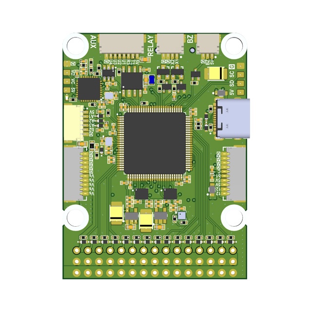
Flight Controller
Built around the STM32H743, the flight controller provides dual IMUs with hardware signal filtering, dual switchable camera inputs, and relay-controlled power outputs.
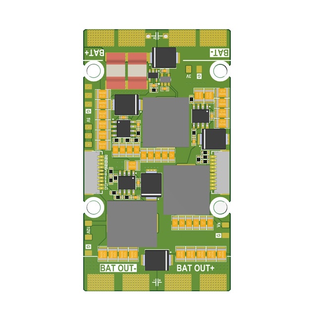
Power Distribution Board (PDB)
Features
- 4S–12S power input
- 5V 5A output
- 5/6/7/9V 5A adjustable output
- 12V 5A output
- 3.3V 1A output
- 0.1 mOhm current sensor
- 36 x 39 mm mounting holes
- 42 x 75 mm board dimensions
Other
| Function | Pin | Notes |
|---|---|---|
| USB D- | PA11 | |
| USB D+ | PA12 | |
| SWDIO | PA13 | Debug |
| SWDCLK | PA14 | Debug |
| Buzzer | PA15 | TIM2 CH1 |
| LED | PD11 | Status |
| IMU clock | PE6 | TIM15 CH2, external clock for IMUs |
| Video NRST | PE3 | OSD/VTX reset |
| Video BOOT | PC13 | Shared with AUX 4 |
Full Pinout Reference
Port A (PA)
| Pin | Function | Alternate |
|---|---|---|
| PA0 | SERVO 15 | TIM5 CH1 |
| PA1 | SERVO 14 | TIM5 CH2 |
| PA2 | SERVO 13 | TIM5 CH3 |
| PA3 | SERVO 12 | TIM5 CH4 |
| PA4 | IMU 1 INT | |
| PA5 | SPI 1 CLK | |
| PA6 | SPI 1 MISO | |
| PA7 | SPI 1 MOSI | |
| PA8 | SERVO 3 | |
| PA9 | SERVO 2 | |
| PA10 | SERVO 1 | |
| PA11 | USB N | |
| PA12 | USB P | |
| PA13 | SWDIO | |
| PA14 | SWDCLK | |
| PA15 | BUZZER | TIM2 CH1 |
Port B (PB)
| Pin | Function | Alternate |
|---|---|---|
| PB0 | SERVO 9 | |
| PB1 | SERVO 8 | ADC1 IN5 |
| PB2 | IMU 1 CS | |
| PB3 | AUX 2 | |
| PB4 | SERVO 10 | |
| PB5 | SERVO 11 | |
| PB6 | I2C 1 SCL | |
| PB7 | I2C 1 SDA | |
| PB8 | FDCAN RX | TIM16 CH1 |
| PB9 | FDCAN TX | TIM17 CH1 |
| PB10 | I2C 2 SCL | |
| PB11 | I2C 2 SDA | |
| PB12 | Serial 5 RX | |
| PB13 | Serial 5 TX | |
| PB14 | Serial 1 TX | |
| PB15 | Serial 1 RX |
Port C (PC)
| Pin | Function | Alternate |
|---|---|---|
| PC0 | ADC 2 | ADC1 IN10 |
| PC1 | ADC 1 | ADC1 IN11 |
| PC2_C | ADC 3 | ADC3 IN0 |
| PC3_C | VBAT2 / 21 | ADC3 IN1 |
| PC4 | ESC CURR | ADC1 IN4 |
| PC5 | VBAT / 21 | ADC1 IN8 |
| PC6 | Serial 6 TX | TIM3 CH1 |
| PC7 | Serial 6 RX | TIM3 CH2 |
| PC8 | SDMMC D0 | TIM3 CH3 |
| PC9 | SDMMC D1 | TIM3 CH4 |
| PC10 | SDMMC D2 | |
| PC11 | SDMMC D3 | |
| PC12 | SDMMC CK | |
| PC13 | VIDEO BOOT / AUX 4 |
Port D (PD)
| Pin | Function | Alternate |
|---|---|---|
| PD0 | Serial 4 RX | |
| PD1 | Serial 4 TX | |
| PD2 | SDMMC CMD | |
| PD3 | RELAY 1 | |
| PD4 | RELAY 2 | |
| PD5 | Serial 2 TX | |
| PD6 | Serial 2 RX | |
| PD7 | AUX 1 | |
| PD8 | Serial 3 TX | |
| PD9 | Serial 3 RX | |
| PD11 | LED | |
| PD12 | SERVO 7 | TIM4 CH1 |
| PD13 | SERVO 6 | TIM4 CH2 |
| PD14 | SERVO 5 | TIM4 CH3 |
| PD15 | SERVO 4 | TIM4 CH4 |
Port E (PE)
| Pin | Function | Alternate |
|---|---|---|
| PE0 | Serial 8 RX | |
| PE1 | Serial 8 TX | |
| PE2 | CAMERA SWITCH | |
| PE3 | VIDEO NRST | |
| PE4 | FDCAN SILENT | |
| PE5 | AUX 3 | TIM15 CH1 |
| PE6 | IMU CLK IN | TIM15 CH2 |
| PE7 | Serial 7 RX | |
| PE8 | Serial 7 TX | |
| PE9 | Serial 7 RTS | |
| PE10 | Serial 7 CTS | |
| PE11 | IMU 2 INT | TIM1 CH2 |
| PE12 | SPI 4 CLK | TIM1 CH2 |
| PE13 | SPI 4 MISO | TIM1 CH3 |
| PE14 | SPI 4 MOSI | TIM1 CH4 |
| PE15 | IMU 2 CS |