KiwiH743 12S Flight Controller

Overview
The KiwiH743 is a high-performance flight controller based on the STM32H743 MCU, designed for advanced UAV applications. It combines powerful processing, flexible connectivity, and rich sensor support, optimized for ArduPilot firmware.
It is the next generation of the KiwiF405 family, offering 2MB flash, 480 MHz CPU clock, extended UART/SPI/I2C buses, and support for dual IMUs, barometer, and OSD integration.
Premium features: GPS-less takeoff, IRC Tramp VTX control, VRX integration (TBS Fusion, Skyzone Steadyview).
Firmware
- ArduPilot KiwiH743.zip
- ArduPilot (SD card) KiwiH743-sdcard.zip
- Betaflight
SD Card Version
The KiwiH743 has a built-in 16 MB DataFlash chip for logging, but if you need more storage (longer flights, detailed logs), you can connect an external SD card module via the SPI1 interface.
Step 1 — Flash SD card firmware
Download and install KiwiH743-sdcard.zip. This firmware disables the onboard DataFlash and enables FATFS file system on the SD card. All logging will go to the SD card instead.
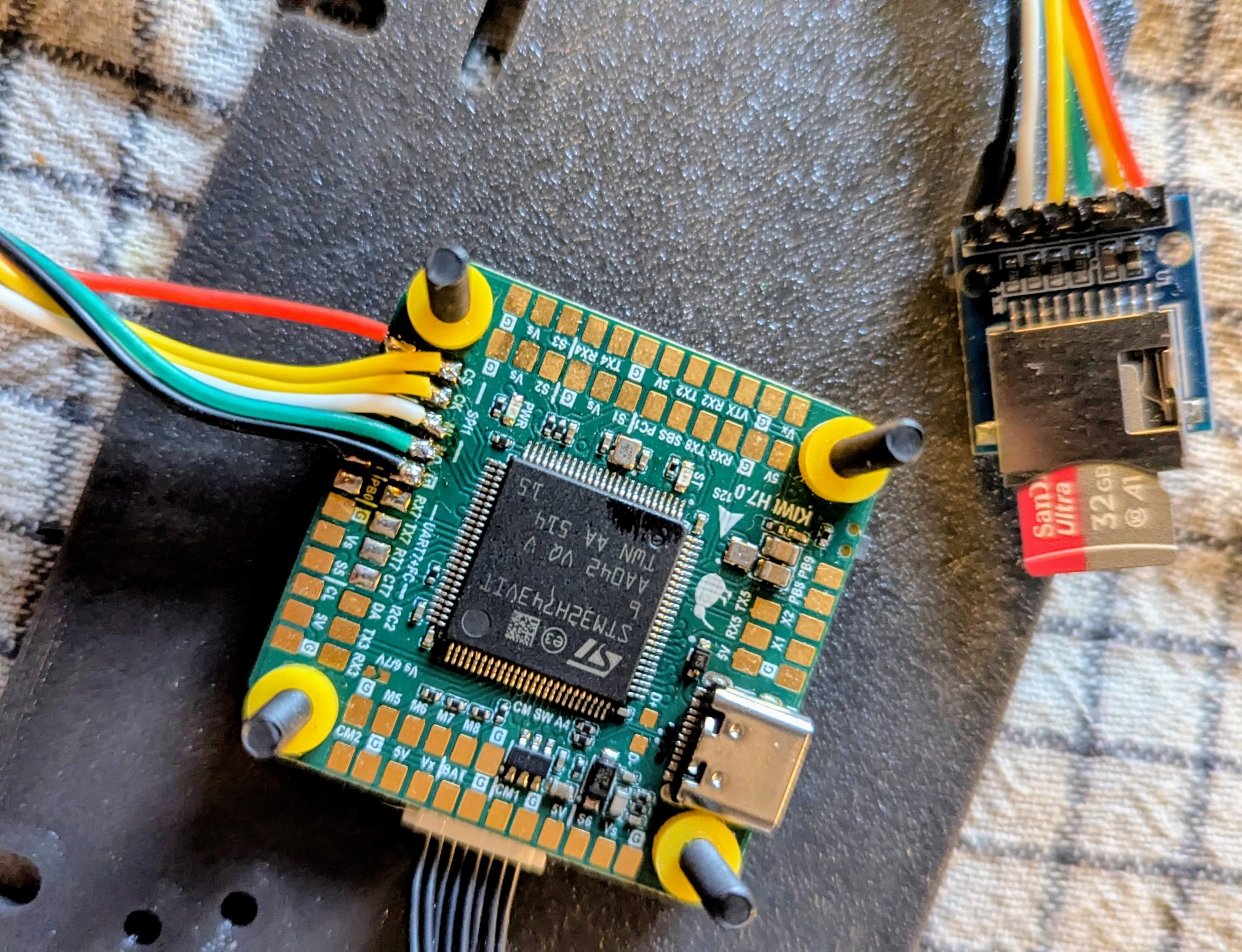
Step 2 — Wire SD card module to SPI1
Connect a 5V-tolerant SPI micro-SD breakout module to the SPI1 pads on the board:
  KiwiH743 (SPI1)           SD Card Module
 ┌──────────────┐          ┌──────────────┐
 │ PA5  (SCK)  ─┼──────────┼─ SCK         │
 │ PA6  (MISO) ─┼──────────┼─ MISO (DO)   │
 │ PA7  (MOSI) ─┼──────────┼─ MOSI (DI)   │
 │ PA4  (CS)   ─┼──────────┼─ CS          │
 │ 5V          ─┼──────────┼─ VCC         │
 │ GND         ─┼──────────┼─ GND         │
 └──────────────┘          └──────────────┘
| FC Pad (SPI1) | Pin | SD Card Module |
|---|---|---|
| SCK | PA5 | SCK (Clock) |
| MISO | PA6 | MISO / DO |
| MOSI | PA7 | MOSI / DI |
| CS | PA4 | CS |
| 5V | — | VCC |
| GND | — | GND |
Use a 5V-tolerant SD card breakout with an onboard voltage regulator. We can ship one with the board upon request — just mention it when ordering.
Format the card as FAT32 before first use.
Features
- Dual IMUs: ICM-42688P + ICM-45686 with EKF3 dual-source fusion
- BMP388 barometer, external compass support (I²C probing)
- Integrated OSD (MAX7456-compatible via SPI4)
- 14 PWM outputs (8 motors + 6 servos), DShot bidirectional on M1–M4
- 7 hardware UARTs + 2 USB ports (OTG1 MAVLink, OTG2 HiSpeed serial)
- 16 MB DataFlash + external SD card slot
- Visual odometry, external AHRS, GPS moving baseline support
- Gyro FFT for vibration analysis
- INS temperature calibration
- Guided (NoGPS), FlowHold, OpticalFlow modes
Technical Specifications
- MCU: STM32H743VIT6 (ARM Cortex-M7, 480 MHz, 2048 KB flash)
- Crystal: 16 MHz external oscillator
- IMU1: ICM-42688P (SPI6, rotation YAW_180)
- IMU2: ICM-45686 (SPI2, rotation YAW_270)
- Barometer: BMP388 (I2C2, address 0x76)
- OSD: MAX7456-compatible (SPI4)
- DataFlash: 16 MB (SPI3)
- LED: PE4 (active low)
- Dimensions: 36×36 mm, mounting 30.5×30.5 mm
Serial Ports
| Port | ArduPilot | Default Protocol | Pins | Notes |
|---|---|---|---|---|
| USB | SERIAL0 | MAVLink | PA11, PA12 | OTG1 Full Speed |
| USART1 | SERIAL1 | ESC Telemetry (115200) | PA10 | RX only |
| USART2 | SERIAL2 | SmartAudio (115200) | PD5, PD6 | NODMA |
| USART3 | SERIAL3 | — | PD8, PD9 | |
| UART4 | SERIAL4 | — | PD1, PD0 | |
| UART5 | SERIAL5 | MAVLink1 (57600) | PB6, PD2 | NODMA |
| UART7 | SERIAL7 | MAVLink2 | PE8, PE7 | RTS: PE9, CTS: PE10 |
| UART8 | SERIAL8 | RC Input | PE1, PE0 | SBUS/DSM |
| USB HS | SERIAL9 | — | OTG2 HiSpeed |
RC input: SBUS/DSM on PE11.
GPIOs, Relays, and AUX
Dedicated GPIO Pads
| Pad | Pin | GPIO | Default | ArduPilot Relay Config |
|---|---|---|---|---|
| CAM SW | PA8 | 100 | RELAY1 | RELAY1_PIN=100 (hwdef default) |
| RELAY1 | PD4 | 101 | Output LOW | RELAY2_PIN=101, RELAY2_FUNC=1 |
| RELAY2 | PB7 | 102 | Output LOW | RELAY3_PIN=102, RELAY3_FUNC=1 |
| LED | PE4 | 90 | Status LED | — |
Note:
RELAY1_PINdefaults to GPIO 100 (Camera Switch pad, PA8), not the pad labeled “RELAY1” (PD4, GPIO 101). This is set in the hwdef. Adjust if your wiring differs.
PWM Outputs
| Output | Pin | GPIO | Timer | Function | DShot Bidir |
|---|---|---|---|---|---|
| PWM1 | PC6 | 50 | TIM3_CH1 | Motor 1 | Yes |
| PWM2 | PC7 | 51 | TIM3_CH2 | Motor 2 | Yes |
| PWM3 | PC8 | 52 | TIM3_CH3 | Motor 3 | Yes |
| PWM4 | PC9 | 53 | TIM3_CH4 | Motor 4 | Yes |
| PWM5 | PD12 | 54 | TIM4_CH1 | Motor 5 | No |
| PWM6 | PD13 | 55 | TIM4_CH2 | Motor 6 | No |
| PWM7 | PD14 | 56 | TIM4_CH3 | Motor 7 | No |
| PWM8 | PD15 | 57 | TIM4_CH4 | Motor 8 | No |
| PWM9 | PA0 | 58 | TIM5_CH1 | Servo 1 | No |
| PWM10 | PA1 | 59 | TIM5_CH2 | Servo 2 | No |
| PWM11 | PA2 | 60 | TIM5_CH3 | Servo 3 | No |
| PWM12 | PA3 | 61 | TIM5_CH4 | Servo 4 | No |
| PWM13 | PE13 | 62 | TIM1_CH3 | Servo 5 | No |
| PWM14 | PB8 | 63 | TIM16_CH1 | Servo 6 | No |
PWM pins can be reassigned to GPIO via SERVOn_FUNCTION=0 + RELAYn_PIN=<gpio>.
Spare ADC
| Pin | Function |
|---|---|
| PC1 | SPARE2_ADC1 (analog input only) |
Relay Usage
MAVProxy:
param set RELAY2_PIN 101
param set RELAY2_FUNC 1
relay set 0 1    # RELAY1 ON (CAM SW pad HIGH)
relay set 0 0    # RELAY1 OFF
relay set 1 1    # RELAY2 ON (RELAY1 pad HIGH)
Mission waypoint: DO_SET_RELAY — relay number 0-based (0=RELAY1), setting 1=ON / 0=OFF.
Lua:
relay:toggle(0)  -- toggle RELAY1 (CAM SW)
relay:on(1)      -- RELAY2 ON (RELAY1 pad)
relay:off(1)     -- RELAY2 OFF
All GPIO pads default LOW on boot. Use RELAY_DEFAULT params to set initial state.
Power Monitoring
- Battery Voltage: PC5 (ADC1 IN8)
- Battery Current: PB1 (ADC1 IN5)
- Default monitor type: Analog
Sensor Calibration
| Parameter | ArduPilot | Betaflight |
|---|---|---|
| Voltage scale | BATT_VOLT_MULT = 21.0 | voltage_meter_scale = 210 |
| Current scale | BATT_AMP_PERVLT = 142.9 | current_meter_scale = 100 |
Battery Voltage Thresholds (ArduPilot)
| Parameter | 6S | 8S | 12S |
|---|---|---|---|
| Full charge | 25.2 V | 33.6 V | 50.4 V |
BATT_ARM_VOLT | 22.2 | 29.6 | 44.4 |
BATT_LOW_VOLT | 21.0 | 28.0 | 42.0 |
BATT_CRT_VOLT | 19.8 | 26.4 | 39.6 |
Buses
SPI
| Bus | CLK | MISO | MOSI | Usage |
|---|---|---|---|---|
| SPI1 | PA5 | PA6 | PA7 | SD Card (CS: PA4) |
| SPI2 | PB13 | PB14 | PB15 | IMU2 ICM-45686 (CS: PD10) |
| SPI3 | PC10 | PC11 | PC12 | DataFlash (CS: PD3) |
| SPI4 | PE2 | PE5 | PE6 | OSD MAX7456 (CS: PE3) |
| SPI6 | PB3 | PB4 | PB5 | IMU1 ICM-42688P (CS: PC13) |
I2C
| Bus | SCL | SDA | Devices |
|---|---|---|---|
| I2C2 | PB10 | PB11 | BMP388 (0x76), external compass |
Default Frame and Modes
- Default frame: Quadcopter X (FRAME_TYPE=3, BetaFlight-X motor order)
- Motor protocol: DShot (MOT_PWM_TYPE=5)
- BLHeli passthrough: enabled (SERVO_BLH_AUTO=1, mask=15)
- Flight mode channel: CH8
- VTX: enabled, band 6, channel 4
Camera Gimbal Support
KiwiH743 supports camera gimbals out of the box — both servo-based and MAVLink protocol gimbals (CADDX GM3 V2 and compatible).
MAVLink Gimbal
Wire gimbal UART to any free serial port (gimbal TX → FC RX, gimbal RX → FC TX, GND).
| Param | Value | Notes |
|---|---|---|
SERIALx_PROTOCOL | 2 | MAVLink2 |
SERIALx_BAUD | 115 | 115200 bps |
MNT1_TYPE | 6 | Gremsy (reboot after setting) |
MNT1_PITCH_MIN | -120 | GM3 V2 spec: ±120° |
MNT1_PITCH_MAX | 120 | |
MNT1_YAW_MIN | -160 | GM3 V2 spec: ±160° |
MNT1_YAW_MAX | 160 | |
MNT1_RC_RATE | 60 | deg/s for rate control, 0 for angle |
RC Control
Assign RC channels to control gimbal axes:
| Param | Value | Notes |
|---|---|---|
RC6_OPTION | 213 | Mount1 Pitch |
RC7_OPTION | 214 | Mount1 Yaw |
RC8_OPTION | 212 | Mount1 Roll (3-axis gimbals only) |
Example: with MNT1_RC_RATE=60, moving the RC6 stick deflects pitch at 60°/s. Set MNT1_RC_RATE=0 for direct angle control (stick position = gimbal angle).
Gimbal firmware must be V2.0 or higher.
Servo Gimbal
Connect pitch/yaw servos to any Servo PWM outputs (PWM9–PWM14).
| Param | Value | Notes |
|---|---|---|
MNT1_TYPE | 1 | Servo |
SERVOx_FUNCTION | 6 | Mount1 Pitch (assign to desired output) |
SERVOx_FUNCTION | 8 | Mount1 Yaw (assign to desired output) |
MNT1_PITCH_MIN | -90 | |
MNT1_PITCH_MAX | 90 | |
MNT1_YAW_MIN | -170 | |
MNT1_YAW_MAX | 170 | |
MNT1_RC_RATE | 60 | deg/s for rate control, 0 for angle |
Pinout Reference
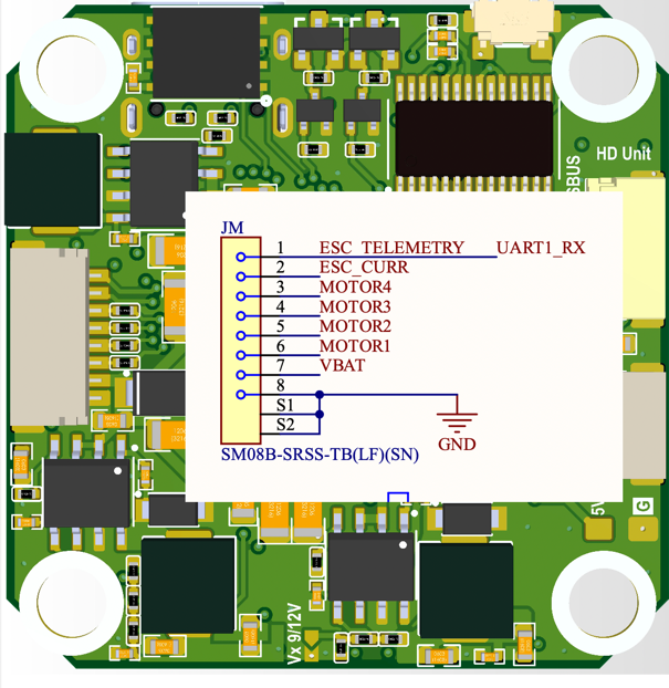
ESC Pins
1 - ESC Telemetry
2 - ESC Current
3 - Motor4
4 - Motor3
5 - Motor2
6 - Motor1
7 - VBAT
8 - GND